
| Air Conditioning Systems
Click here for a Mechanic's Perspective |
|
|---|---|
| The air conditioning system consists of three air cycle machines (ACM) or packs, located in the lower forward unpressurized section of the airplane. Each of the packs uses air from the corresponding pneumatic system, but since air can be directed from any pneumatic system to any other pneumatic system through the 1-2 and 1-3 isolation valves, any pack can be supplied from any bleed source. Pneumatic air serves two purposes. One, it is the power source for driving the air cycle machine; and two, it is the source of heat for the air conditioning system. |
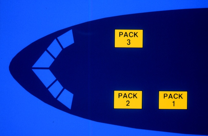 |
| This is the number one air conditioning system, which except for trim air, is typical of all three systems. When the rotary pack switch is off, the flow control valve is electrically held closed and the PACK OFF light is disarmed. When the pack switch is turned to auto or manual, the PACK OFF light is armed and the flow control valve is permitted to open, provided sufficient pneumatic air is available. In auto or manual, there are two conditions that will close the flow control valve and cause the PACK OFF light to illuminate. One condition is insufficient pneumatic supply air, and the other is an overheat inside the pack.The overheat protection will be discussed in more detail shortly. In the event of an electrical failure, if the pack switch is off, the holding circuit will be de-energized and the pack valve will fail open. |
 |
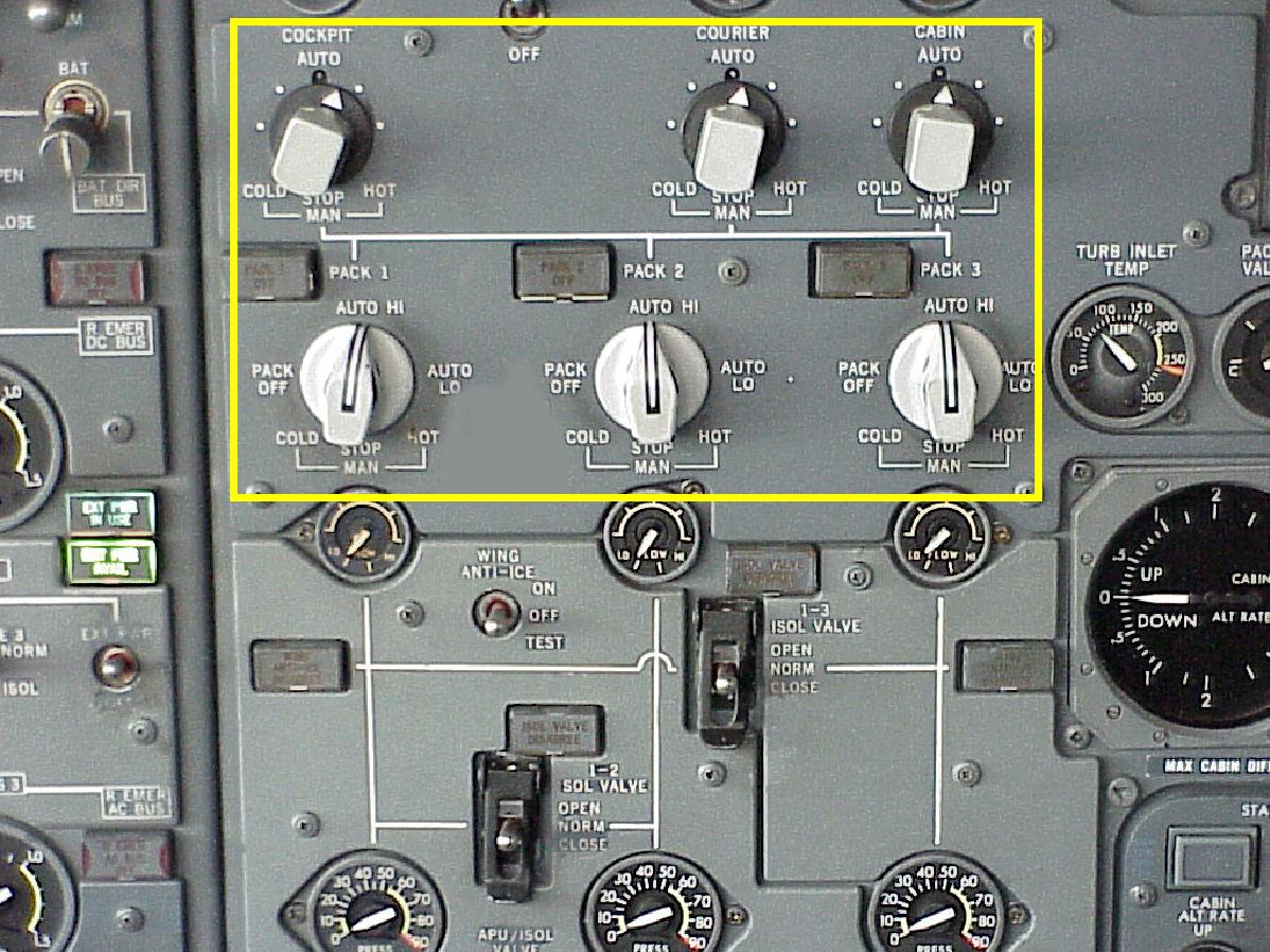
| The pack switch also incorporates an automatic temperature function provided two conditions are met. First, the pack switch must be in one of the auto positions. Second, at least one compartment temp selector must be in the auto position. Of course, if only one compartment temp selector is in auto, then the associated packs will zero in only on this compartment temperature. Except for an unusual condition, all pack switches and all compartment temp selectors should be in auto. They are designed to work together. In auto, the packs supply the coldest demand of any compartment in the airplane. This results in overcooling of the other compartments. Hot trim air is added to these overcooled compartments to bring the temperatures up to desired levels. |
 |
| The auto-low position (on some aircraft) also provides automatic temperature control but at a reduced flow rate. Some fuel savings are realized in the low position, but at the expense of reduced cabin air circulation. |
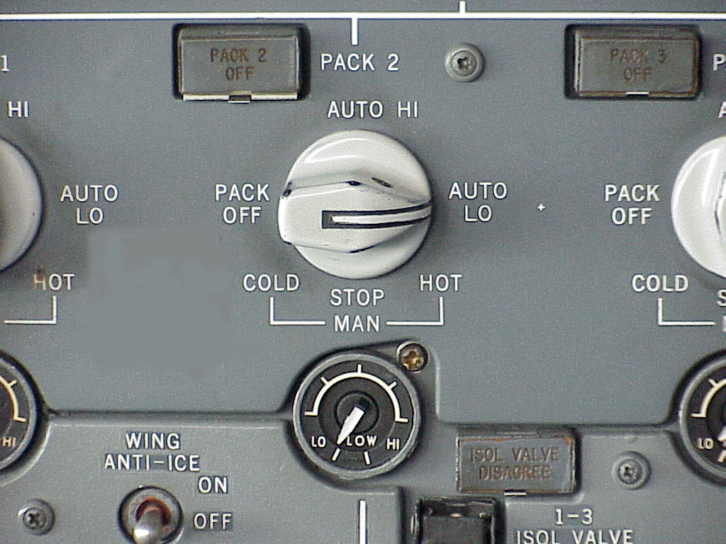 |
| In the manual position, the auto temp controller is deactivated on that pack, and direct control of the pack temp (turbine bypass) valve and the inlet and exhaust doors of the heat exchanger is possible. | 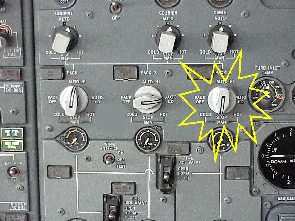 |
The Air Cycle Process | |
| The Packs cool the bleed air through the Air Cycle Process (rapid expansion). Hot bleed air enters the pack compressor inlet from the pneumatic system through the flow control valve. Downstream of the flow control valve on packs 1 and 3 is the tap-off for trim air. You can see from this picture that the flow control valve for packs 1 or 3 must be open for pneumatic air to be supplied to the trim air system even though trim air does not go through the air cycle machine. (Trim Air will be discussed later). Next, the air flows through the compressor of the air cycle machine, where it is compressed and heated, or if max heating is required, bypasses the compressor. | 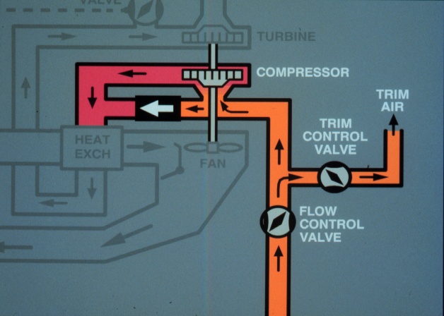 |
| Upon leaving the compressor section of the pack, the air flows through a heat exchanger. Cool external air from the inlet scoops passes over the heat exchanger, cools the compressed air, and is vented through the exhaust duct as hot air. On the ground, a fan, driven by the turbine on a common shaft with the compressor, draws outside air across the heat exchanger. | 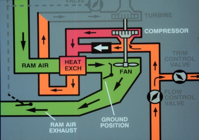 |
| After leaving the heat exchanger, air is routed either through the turbine and water separator, or bypassed around the turbine. The pack temperature valve (Turbine Bypass Valve) determines how much air will pass through the turbine. The compressed air rapidly expands and cools at is passes through the turbine section. The water seperator - also called a coalescer - swirls the air rapidly to extract water vapor and dry the cool air. This 'coalesced' water is then sprayed across the heat exchanger to further enhance cooling. The cool, dry air is then routed to the conditioned air manifold for distribution throughout the aircraft. The temperature drop realized between the turbine inlet and and turbine discharge is almost always 50* Celsius. | 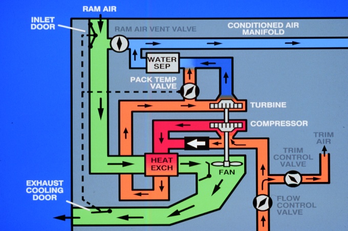 |
| Each pack is protected from overheat by both thermal switches and fuse plugs that sense high turbine inlet or high compressor discharge temperature. The thermal switches open or close the flow control valve to control pack temperature within preset limits. The PACK-OFF light will cycle as the valve opens and closes. If the thermal switches or manual control will not control the temperature, the fusible plugs will melt forcing the flow control valve closed. The PACK-OFF light will come on and the pack cannot be reset in flight. Low pressure in the pneumatic system supplying a pack will also cause the flow control valve to close and the PACK-OFF light to come on. | 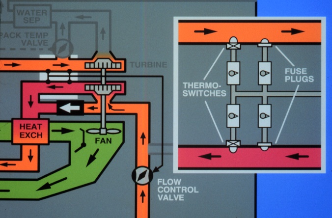 |
| Located to the right of the number 3 pack switch is a means of monitoring individual pack operation. It consists of three gauges: a Turbine Inlet Temperature gauge, a Pack Temperature Valve Position indicator, and a Pack Discharge Temperature gauge. To the right of the gauges is a selector switch to determine which pack the gauges are monitoring. | 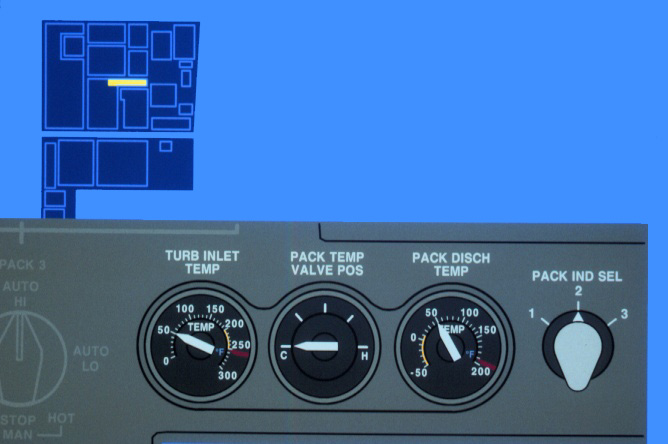 |
| The Turbine Inlet Temperature gauge indicates the temperature of the air prior to the turbine stage of the air cycle machine. |  |
| The Pack Temperature Valve Position indicator shows the position of the pack temperature valve and the inlet and exhaust door position since all three are driven by the same motor. Temperature valve cold means doors open, temperature valve hot means doors closed. | 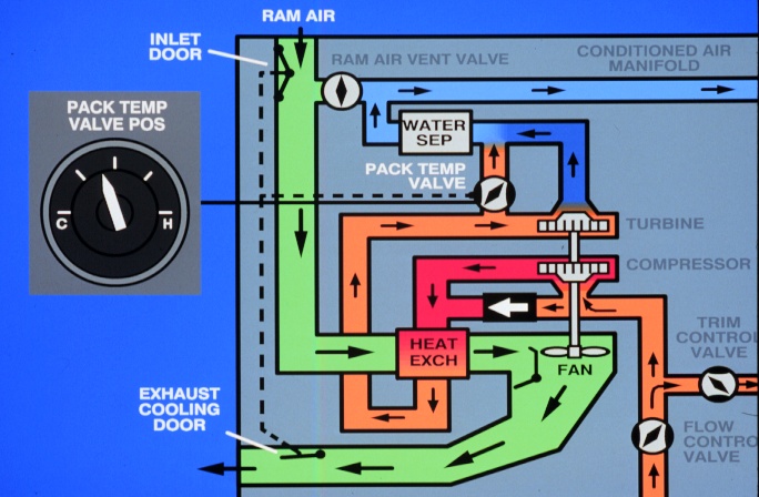 |
| With the pack temperature valve in the Full Cold position (valve closed), the majority of airflow is through the air cycle machine. The ram air inlet and exhaust doors would be fully open since they are driven by the same motor. The resulting output would be maximum cooling. In this condition the pack discharge temperature is colder than the turbine inlet temperature. | 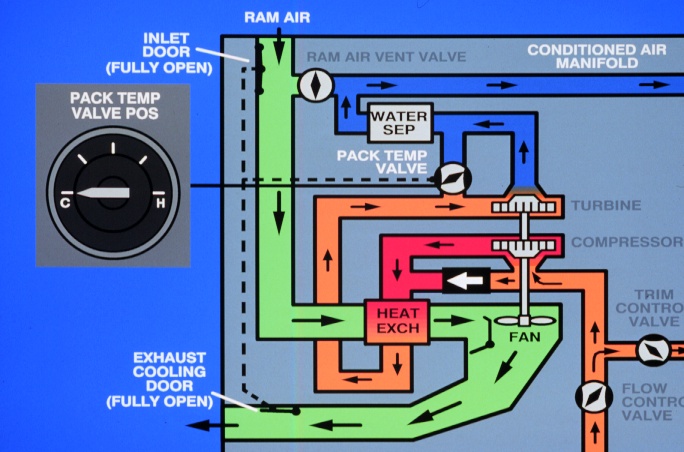 |
| With the pack temperature valve in the Full Hot Position, valve open, the majority of airflow bypasses the air cycle machine. The ram air inlet and exhaust doors are closed, thus resulting in hot air output. In this case the pack discharge and turbine inlet temperature would be nearly the same. | 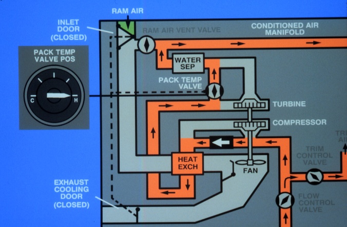 |
| Finally, the Pack Discharge Temperature gauge indicates the temperature of the conditioned air as it leaves the pack. Notice the arc on the gauge from 10°F and below. The packs are capable of putting out air as cold as 10°F, which of course is well below freezing. An anti-ice valve injects warm air just downstream from the turbine discharge, when moisture is present, to prevent ice formation in the water separator. However, if no moisture is present in the air, no warm air is injected. | 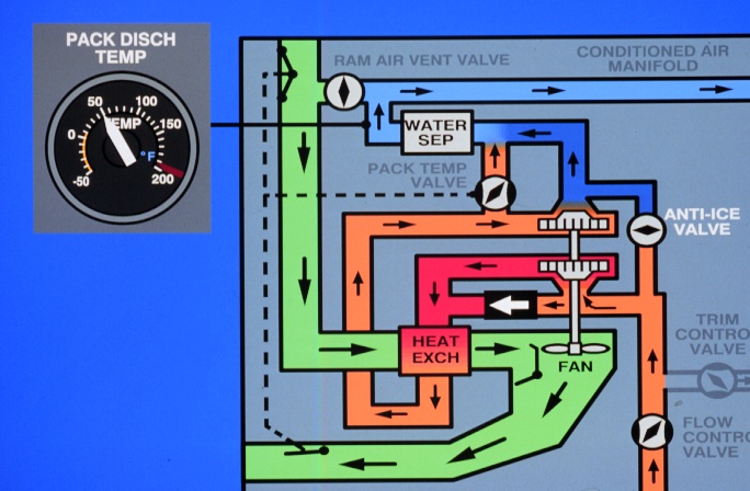 |
The Trim Air System | |
| The Trim Air System, shown here in red, mixes hot pneumatic air from systems one and three with cooler conditioned air from the packs in the individual compartment ducts. For example, pack one is supplying cool air for the cockpit; and its trim air valve is closed. Additionally, packs two and three are supplying cool air to satisfy the center compartment demand, and its trim air valve is closed. The Trim Air System is adding hot air to the other two cabin ducts. | 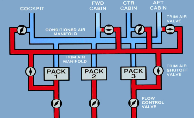 |
| The Trim Air Switch opens both systems one and three trim air supply valves. These trim air supply valves are not represented on the second officers panel schematic layout. In order for the trim air system to be pressurized, one or both of the trim air valves must be open, the associated pack must be on and the respective pneumatic manifold must be pressurized. | 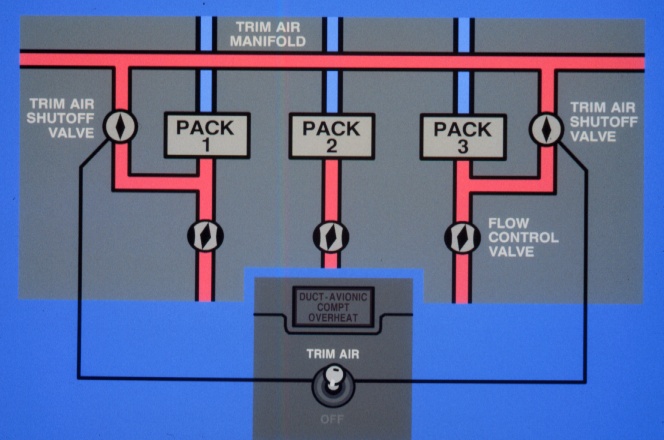 |
| Just above the manifold line are the four individual compartment temperature selectors and their associated trim air valve position indicators. The compartment temperature selectors may be positioned anywhere in the auto range to select the desired temperature. When any compartment temperature selector is in auto, the appropriate pack or packs and the trim air valve for that compartment are automatically controlled to achieve and maintain the selected temperature. However, if the trim air system is not pressurized for any reason, the four individual trim air valves, whose positions are shown on each of the four indicators, may continue to modulate, but will have no effect on duct temperature regardless of position, since no hot air is being supplied to them. | 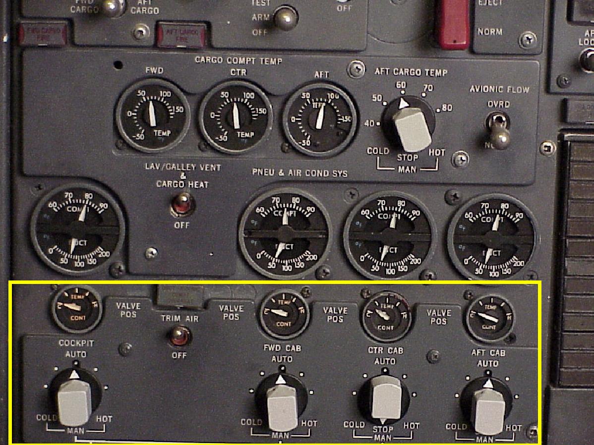 |
| Some aircraft have the galley located under the first class cabin compartment. You will notice that there are five compartments instead of four. For air conditioning purposes, the lower galley is added as an additional compartment. | 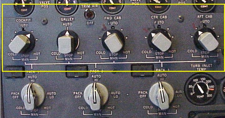 |
| At the top of the panel are individual compartment and duct temperature gauges. The duct temperature gauges on the bottom half show pack discharge temperature if the trim air valve is closed, or the combined warmer mixture of pack air and trim air, if the trim air valve is open. The top half shows the temperature sensed in each compartment. | 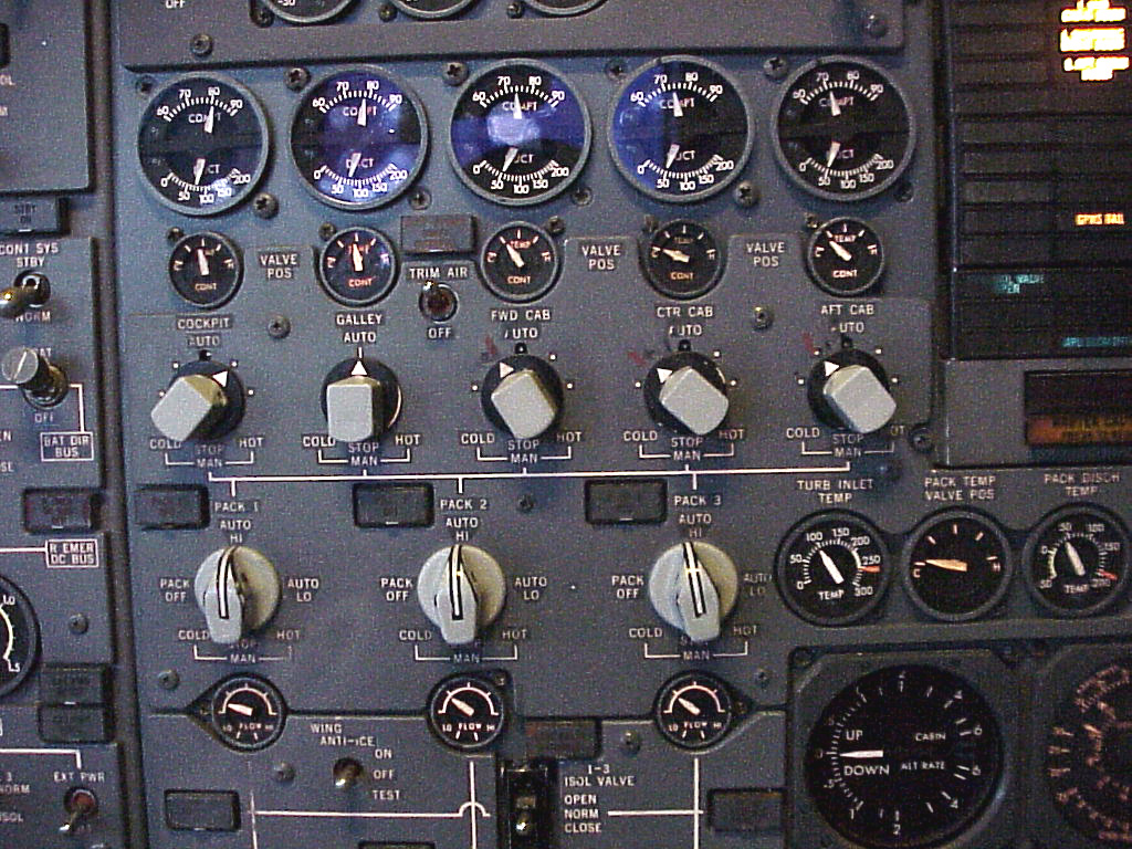 |
Air Recirculation Fans | |
| A cabin air recirculation system is installed on the upper galley airplanes. Four recirculation fans, located above the cabin ceiling, draw cabin air through filters in a recirculation manifold. The air is then ported into each of the three main compartment distribution ducts for return to the forward, center, and aft cabin zones. | 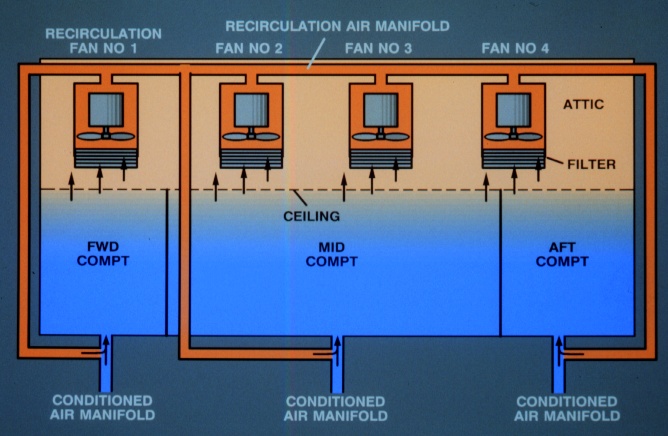 |
| The recirculation fans are controlled by these switches, located on the Second Officer's upper panel. The recirc fan switches are held to the on position electrically and will trip to the off position along with the galleys when a generator overload occurs. Normal power interruptions may also cause the recirc fan switches to trip to the off position. |  |